-
- Inauguration Of The 25th KR Chairman & CEO LEE Hyungchul
- New Year’s Speech 2023
- KR Unveils Port State Control Mobile App ‘KR PSC ADVISER’
- KR Classes Six New Doun Kisen Bulk Carriers
- KR Awards Approval In Principle To Louis Dreyfus Ports & Logistics’ FRESH vessel
- KR Signs MOU With KAMCO For Fostering ESG Management I The Shipping Sector
- KR Shares Its Green Insights In KR Decarbonization Magazine
- KR Publishes 2022 ESG Report
-
- Conventions to be effective on or after Jan. 1, 2023
- ISM, ISPS, MLC,2006 FAQ - 2022
- MEPC 79 - News Flash
- Changes in the Certificate issuance system related to the transportation of solid bulk cargoes
- Notice of Amendments to the KR Technical Rules (Rule/Guidance, Part 9)
- Notice of Amendments to the KR Technical Rules (Rule/Guidance, Part 1)
- Notice of Amendments to the KR Technical Rules (Guidance for Pt.7 Ch.6)
- Inauguration Of The 25th KR Chairman & CEO LEE Hyungchul
- New Year’s Speech 2023
- KR Unveils Port State Control Mobile App ‘KR PSC ADVISER’
- KR Classes Six New Doun Kisen Bulk Carriers
- KR Awards Approval In Principle To Louis Dreyfus Ports & Logistics’ FRESH vessel
- KR Signs MOU With KAMCO For Fostering ESG Management I The Shipping Sector
- KR Shares Its Green Insights In KR Decarbonization Magazine
- KR Publishes 2022 ESG Report
- Conventions to be effective on or after Jan. 1, 2023
- ISM, ISPS, MLC,2006 FAQ - 2022
- MEPC 79 - News Flash
- Changes in the Certificate issuance system related to the transportation of solid bulk cargoes
- Notice of Amendments to the KR Technical Rules (Rule/Guidance, Part 9)
- Notice of Amendments to the KR Technical Rules (Rule/Guidance, Part 1)
- Notice of Amendments to the KR Technical Rules (Guidance for Pt.7 Ch.6)
-
- Inauguration Of The 25th KR Chairman & CEO LEE Hyungchul
- New Year’s Speech 2023
- KR Unveils Port State Control Mobile App ‘KR PSC ADVISER’
- KR Classes Six New Doun Kisen Bulk Carriers
- KR Awards Approval In Principle To Louis Dreyfus Ports & Logistics’ FRESH vessel
- KR Signs MOU With KAMCO For Fostering ESG Management I The Shipping Sector
- KR Shares Its Green Insights In KR Decarbonization Magazine
- KR Publishes 2022 ESG Report
-
- Conventions to be effective on or after Jan. 1, 2023
- ISM, ISPS, MLC,2006 FAQ - 2022
- MEPC 79 - News Flash
- Changes in the Certificate issuance system related to the transportation of solid bulk cargoes
- Notice of Amendments to the KR Technical Rules (Rule/Guidance, Part 9)
- Notice of Amendments to the KR Technical Rules (Rule/Guidance, Part 1)
- Notice of Amendments to the KR Technical Rules (Guidance for Pt.7 Ch.6)

Writers
Choi Hyosun Senior Surveyor
Ship & Offshore Technology Team
Liquefied Natural Gas (LNG) is a cleaner fossil fuel and demand for LNG carriers and LNG-fueled ships is greatly increasing. LNG is carried in a cryogenic state where natural gas is liquefied at -163°C. Therefore, it is necessary to prevent damage and leakage of cryogenic piping devices used for storage, transportation and unloading. The IGC&IGF Code requires piping stress analysis in accordance with internationally recognized codes for piping systems of LNG carriers and LNG-fueled ships with a design temperature of -110℃ or colder or where a high-pressure fuel piping system is applied.
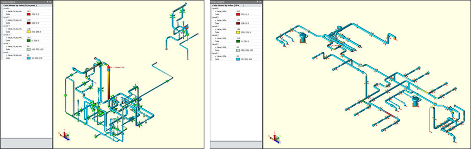
Fig. 1 Illustration for Cryogenic Piping Stress Analysis
Piping stress analysis is a review and verification process that determines whether the piping system satisfies the minimum requirements of relevant laws and codes and structural safety when designing the piping system. The safety of the piping layout and support position is confirmed by considering the load and deformation applied to the piping system, such as self-weight, internal pressure, wind, thermal, and deformation of the hull due to sagging/hogging.
Cryogenic piping stress analysis uses CAESAR II, which widely supports international codes such as ASME and API.
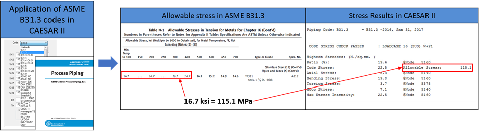
Fig. 2 CAESAR II automatically supports ASME B31.3 allowable stress
A code is a regulation intended to protect the life and property of the end user. This is mandatory and specifies the minimum requirements for materials and products, inspection, test requirements, and operation procedures. Cryogenic piping stress analysis applying the actual operating environment is performed based on ASME B31.3 Process Piping Code.
The ASME Code outlines stress evaluation in several categories. This means that various failed uses of piping materials, such as excessive plastic deformation, excessive elastic deformation, brittle fracture, and stress rupture, appear differently depending on the type and form of stress acting on the pipe.
The characteristics of primary stress and secondary stress are as follows:
The primary stress is that which is generated to balance the force and moment when a load, such as the weight of the pipe, pressure, or wind acts on the piping system, and there are no self-limiting factors. For example, when internal pressure is applied to a pipe, stress is generated. Even if the diameter of the pipe increases due to deformation, the same stress exists as long as the internal pressure remains. When a load is applied to the pipe, stress is generated, and the stress is maintained even if deformation occurs. Representative primary stresses include membrane stress (uniform normal stress) and bending stress. The safety against the primary stress should be evaluated in the Sustained Case and Occasional Case and compared with the allowable pressure on the pipe material.
The secondary stress involves self-limiting as a stress generated by the constraint of the piping system. Self-limiting is a phenomenon in which stress is advantageously redistributed when local yielding or small deformation occurs. It is not a stress generated to make the equilibrium of force and moment concerning external force. Even if a pressure greater than the yield stress of the material is applied, damage to the piping system does not necessarily occur rapidly. Representative secondary stresses include general thermal stress and bending stress in gross structural discontinuity. The safety against the secondary stress should be evaluated in the Expansion case and compared with the allowable pressure range.
In particular, among the load cases specified in ASME B31.3, the operating case is a typical example of distinguishing and evaluating primary and secondary stresses. The load combination is composed of ‘self-weight (W) + internal pressure (P) + thermal (T)’. Among them, self-weight and internal pressure are load components that generate primary stress, and thermal is a load component that causes secondary stress, and they are combined together. Therefore, in this case, stress is not evaluated, and only displacement and force are calculated to determine safety.
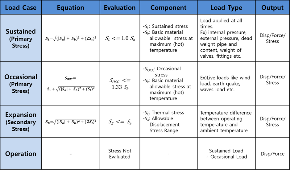
Table. 1 Load case defined by ASME B31.3
By calculating the four load cases defined in ASME B31.3, Stress, Displacement, and Restraint (acting on the support) can be derived, as shown in Table.2. The main review items based on this are as follows.
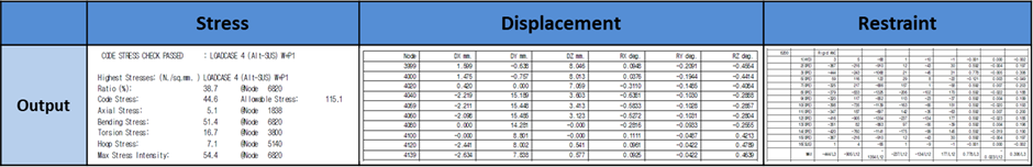
Table.2 Output Data
In the stress category, check whether the maximum stress is within the allowable stress specified in ASME B31.3. In addition, safety should be determined by considering the location of maximum stress, the load case that causes the maximum stress, and the ratio of the maximum stress to the allowable level.
When stress occurs in the piping system, displacement also takes place depending on the magnitude of the stress, the direction of the stress, and the type of support that exists. Therefore, the behavior of the pipe can be predicted by referring to Table.2 ‘Displacement’. In particular, it should be determined whether the displacement caused by the piping weight is excessive in the vertical or horizontal direction and whether the displacement value in an Expansion Case or Occasional Case is too excessive to interfere with the surrounding structures.
As shown in Table.2 ‘Restraint’, considering the direction and magnitude of the load acting on the pipe support, it is possible to determine whether excessive load occurs and how to reinforce the support.