Writers
Islam MD Shafiqul and Kim Beom-il
Ship & Offshore Technology Team
Background
In recent years, the market demand for small and medium sizes gas carriers/bunkers/barges has increased for short and medium distance trade. Also, the demand for eco-friendly gas-fueled vessels is growing rapidly due to IMO Sulphur cap.
One of the promising solutions to meet this growing demand is to use independent Type-C tanks for gas carrier or fueled vessels. IMO Type-C tank is normally a cylindrical or spherical pressure vessel having design pressure higher than 2 bar. It is designed and built to meet the requirements of recognized pressure vessel standards or codes such as ASME Boiler and Pressure Vessel (BPV) Code, which are supplemented by additional classification society requirements and statutory regulations.
Due to enhanced design factor, this tank is considered as a leak free tank and hence no secondary barrier is required. Type C is the dominant design for LNG fueled ships, but it is also used in small LNG, Ammonia or LPG carriers and always used for semi-pressurized or fully pressurized gas carriers.
There are also numerous ongoing research projects in the world on the application of Type-C tanks for liquified hydrogen carrier/fueled ships. For cylindrical or spherical tanks, there are two types of tank support saddles such as fixed and sliding. The fixed support anchors the tank while the sliding support allows the tank to expand and contract as needed.
Type-C tanks can be single-walled or double-walled tanks. Single-walled tanks aregenerally covered outside by an insulation layer and insulation wood is placed between the support saddle and tank structure. Double-walled tanks are equipped with vacuum insulation and insulation wood/plastic support is placed between inner and outer tank. Double-walled tanks have a longer pressure holding time compared to single walled tank.
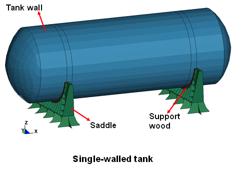
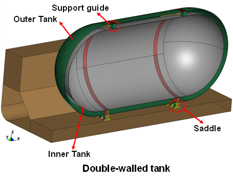
Figure 1: Basic design for IMO Type C tank
Combination of Design Loads for Strength Evaluation
The strength evaluation of a Type-C tank requires complex thermal and structural analyses, and theresolution of thermal contact amongst the tank shell, wood, and saddle structures. This study deals with the structure design of the Type-C independent tank intended to use for liquefied natural gas and hydrogen gas. Sequentially coupled thermal-structural analysis is performed applying thermal and mechanical loads and the complexity of thermal contact is resolved.
The design basis for Type-C independent tanks is based on pressure vessel criteria modified to include fracture mechanics and crack propagation criteria. The scantling of the tank is accomplished based on the design pressure. The designed internal pressure is composed of vapor and liquid pressure. The liquid pressure is a result of the combined effects of gravity and acceleration excluding sloshing loads.
Calculations on the loads and stresses in the way of the supports and the shell attachment of the support shall be made. FE stress analysis are performed for assessing yielding strength for each component of a Type-C tank.
The stress analysis considers various loads, including internal and external pressure, dynamic loads caused by ship motion under different loading conditions, thermal loads, sloshing loads, loads associated with ship deflections (if applicable), tank and cargo weight with corresponding support reactions, insulation weight, test loads, cold vacuum pressure (for double-walled tanks), wind impact, wave impacts, and the green sea effect for fuel tanks installed on the open deck.
Typical load cases applied for structural strength analysis of a Type-C tank is given in Table 1.
Load case | Condition | Vapor Pressure, Po | Self-weight | Static | Dynamic | Heel | Thermal | ||
g | ax | ay | az | 30o | |||||
1 | Static | Ο | Ο | Ο | - | - | - | - | Ο |
2 | Acc. Trans. | Ο | Ο | Ο | - | Ο | - | - | Ο |
3 | Acc. Vert. | Ο | Ο | Ο | - | - | Ο | - | Ο |
4 | Acc. Longi. | Ο | Ο | Ο | Ο | - | - | - | Ο |
5 | Heeled | Ο | Ο | Ο | - | - | - | Ο | Ο |
6 | Collision | Ο | Ο | Ο | 0.5g | - | - | - | Ο |
7 | Hydro test | 1.5* Po | Ο | Ο | - | - | - | - | - |
Table 1: Typical Load Cases for (Structuralstrength evaluation)
Example of Yielding Strength Analysis:
The structural strength of a typical Type-C tank and supporting structure is assessed performing FE stress analysis. Accelerations are calculated based on IGC code to determine the dynamic loads. Vapor pressure, self-weight and hydrostatic pressure are considered as additional mechanical loads and IMO temperature condition is applied as thermal loads. Sequentially coupled thermal-structural analysis is accomplished in two steps:
Step 1: thermal analysis to calculate the structure member temperature.
Step 2: stress analysis considering thermal loads in step 1 and mechanical loads.
The tank is loaded with LH2 and hence the temperature of the tank is set to -253oC. Air temperature of 5oC is applied as convective boundary to the saddle structure. Heat is transferred between Type-C tank and the saddle through wood by conduction and appropriate thermal contact is applied between them. The result of thermal analysis is presented in Figure 2.
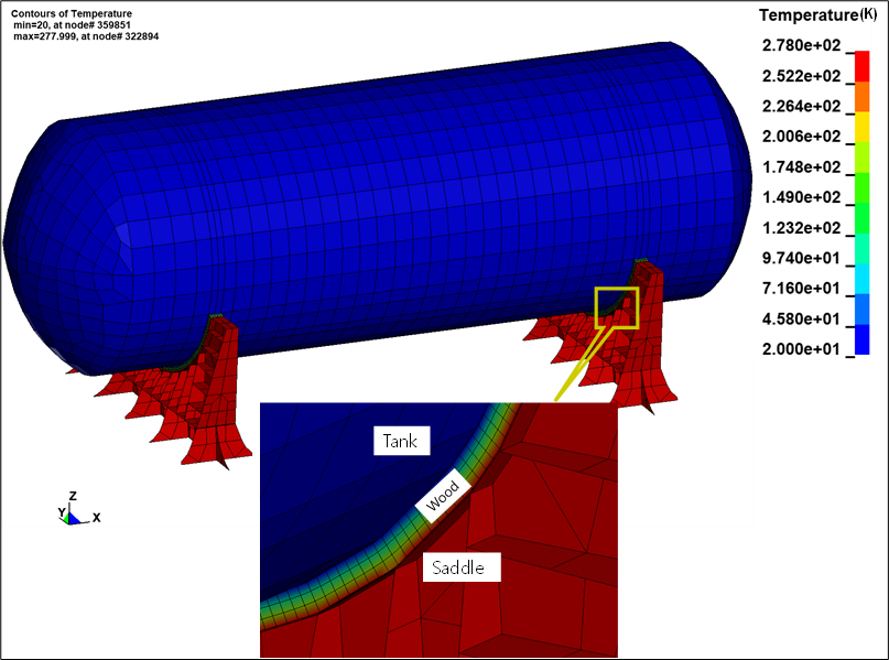
Figure 2: Results of Thermal Analysis of a Typical Type-C Tank
During step 2, the stress analysis takes into account thermal and mechanical loads. One of the saddles supporting the tank is defined as fixed, while the other is defined as having sliding contact. Stresses occur on the tank surface due to internal pressure, and on the fixed saddle due to the application of constraints against thermal movement. The results of the stress analysis are presented in Figure 3.
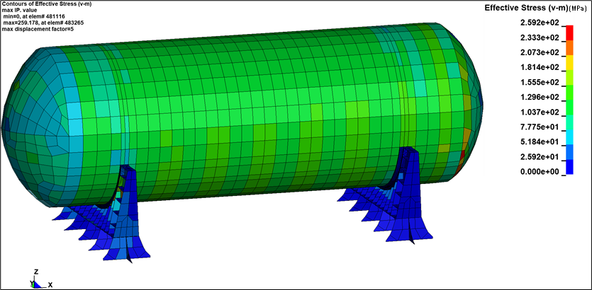
Figure 3: Results of stress analysis applying thermal and mechanical loads
Example of Buckling Strength Analysis:
The thickness and shape of a pressure vessel, which is subjected to external pressure and other loads that induce compressive stresses, should be determined based on established buckling theory applicable to cylindrical vessels.This analysis shall adequately account for the difference in theoretical and actual buckling stress as a result of plate edge misalignment, ovality and deviation from a true circular form over a specified arc or chord length.
The loads for buckling check include, but are not limited to, external overpressure, shell weight, etc. The critical buckling pressure of the cylindrical tank is obtained from linear FE eigenvalue analysis. As an example, Figure 4 presents the buckling mode from eigenvalue analysis. FE results show that the critical external overpressure is 1.93 MPa.
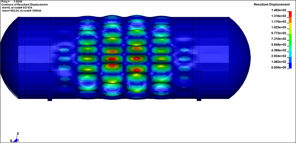
Figure 4: Buckling Mode under External Overpressure
Conclusion
This study introduces the strength evaluation procedure, defines load cases, and provides yielding and buckling analysis results for a typical Type-C tank. The numerical technique for performing sequentially coupled with the thermal-structural analysis considering complex thermal contacts is presented with applied with examples.
The procedure for calculating critical buckling stress using linear FE eigenvalue analysis is also introduced. The insight of this study will be helpful for design and strength analysis of Type-C LNG, LC02 and LH2 carrier/fueled tank.