
Machinery Equipment Research Team
1. Background
As the impact of global warming issues grows globally, the International Maritime Organization (IMO) adopted an initial strategy to reduce greenhouse gas (GHG) emissions from ships at the 72nd session of its Marine Environment Protection Committee (MEPC) in 2018. The goal was to reduce international shipping GHG emissions by more than 50% from 2008 by 2050. In addition, the short-term, medium-term and long-term measure candidates selected for this purpose will be finalized when the final strategy is adopted in 2023. The mid- and long-term measures included various measures for the application of low-carbon and zero carbon alternative fuels for ships, suggesting that a change in ship fuel is inevitable.
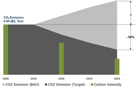
 Figure 1. Initial IMO strategy on reduction of GHG emissions from ships (Figure from KR Decarbonization)
In order for ships to use alternative fuels, it is necessary to develop a new engine propulsion system that considers the characteristics of low-carbon or zero-carbon fuels. To develop a new alternative fuel-applied engine, a new fuel supply system in the cylinder must also be developed. The new system will be analyzed, designed and manufactured based on the target performance of the developed engine and, after evaluating the performance and durability of the trial product with a test rig, a real-life engine performance test will be conducted. Considering the urgency of the technology development, a fuel supply system development and engine application test facilities to support the development and performance evaluation of low-carbon alternative fuel engines was established at the Korea Register of Shipping Green ship Equipment Testing and Certification Center (hereinafter referred to as ‘TCC’).
2. Low-carbon alternative fuel engine development and performance evaluation system
2.1 Establishment of performance evaluation test rig for fuel injection system
The fuel supply method in the engine cylinder differs depending on the combustion method. In the case of the compression ignition method, fuel is injected into the combustion chamber by using a fuel injector. A new fuel injector should be developed for liquid injection of low carbon fuels such as LPG, methanol, and ethanol. The fuel injector is designed and manufactured by calculating and analyzing the amount of fuel according to the engine's development performance goal, and the injection characteristics (injection pressure, injection amount, injection rate, etc.) of the trial product should be analyzed and verified against the design specification.
We established a test rig to analyze the injection characteristics of fuel injectors for medium-speed engines. The test rig consists of a mechanical fuel injector driving part, an injection characteristic measuring part, a fuel supply device, and a sealing oil and lubricating oil supply device. The fuel supply system was configured to supply LPG, methanol, ethanol and diesel among low-carbon fuels and, in the case of sealing oil to prevent fuel leakage from the fuel injector, it was constructed to supply up to 100 bar. A high-precision, high-resolution pressure sensor (2,000 bar) was used to measure the injection characteristics, while a Coriolis-type mass flow meter (1,000 kg/h) was installed at the inlet and outlet ends of the injector to measure the injection amount.
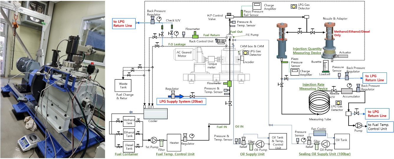
 Figure 2. Test rig for Fuel Injection System (Left) Schematic diagram (Right)
2.2 Establishment storage and supply system for LPG fuel
We established a system that can store and supply LPG in low-carbon alternative fuels. The storage and supply system for LPG fuel is capable of storing 4.9 tons of LPG fuel in the liquid phase and supplying fuel at up to 50 bar g or 1.7 m3/h. A heat exchanger was installed to match the temperature conditions supplied to the engine, while a filter (10 μm) was applied to prevent the inflow of foreign matter into the engine. And a knockout drum was applied to for gas-lquid separation and treatment when purging the LPG fuel inside the pipe when the engine was stopped.
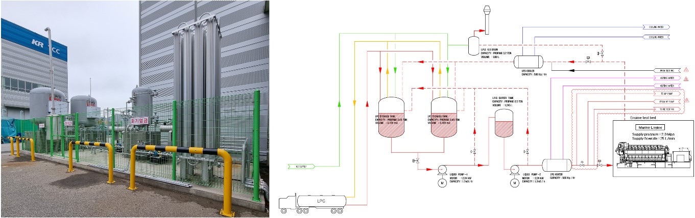
 Figure 3. Storage and supply system for LPG fuel (Left) Schematic diagram (Right)
2.3 Establishment of medium speed test engine for application of development fuel injection system
After evaluating the performance and durability of the developed fuel injection system on the test machine, a test engine for engine application experiments was established. Considering the self-ignition temperature of the low-carbon alternative fuel, which is relatively high compared to diesel, a dual-fuel engine that can form a cylinder atmosphere by using pilot oil supply was selected to test a medium-speed engine that has a rated output of 1,075 kW (@ 950 rpm) from five cylinders. In diesel mode and gas mode, D2 and E2 operation, which is the engine test cycle of IMO NTC 2008, is also possible, while E3 operation is only possible in diesel mode.
 중속 엔진1.jpg)
 Figure 4. Test dual-fuel medium-speed engine
3. Summary and future plan
TCC provides technical support services for low-speed, medium-speed, and high-speed marine engines and related equipment, while technical support has become possible in the entire engine development process through the development of low-carbon alternative fuel engines and the construction of performance evaluation infrastructure. In addition, the construction of the zero-carbon fuel (ammonia) storage system and supply system is scheduled to be completed within the first half of 2023. Through this, technical support will be provided for the development and performance evaluation of alternative fuel engines that can comply with GHG emission regulations.